
Numerical Study of Transverse Fuel Injection in Supersonic Turbulent Crossflow and Sonic Line Angle Analysis
Introduction to Supersonic Combustion and Transverse Fuel Injection
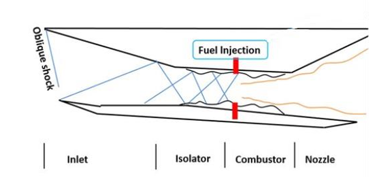
Scramjet engines enable supersonic combustion, essential for maintaining efficiency and minimizing total pressure losses. Unlike conventional engines, scramjets rely on forward motion for air compression and require an initial boost to reach operational speeds.
At hypersonic velocities, airflow compression occurs through oblique shock waves, forming a shock train before the combustor. Unlike ramjets, scramjets avoid a terminating normal shock, keeping the flow supersonic. The key challenge is the short air residence time (milliseconds), limiting fuel-air mixing and combustion efficiency. To address this, flameholders extend residence time and enhance mixing.
Fuel injection strategies include:
- Transverse (Normal) Injection: Fuel is injected perpendicular to airflow, improving turbulence and mixing.
- Parallel (Strut-Based) Injection: Fuel follows the airflow direction, often stabilized by strut-based flameholders.
This study focuses on Transverse Fuel Injection (Jet Injection in Supersonic Crossflow - JISC), analyzing shock-wave interactions, fuel-air mixing, and combustion efficiency in supersonic conditions.
Flow Structures in Transverse Injection and Jet Penetration
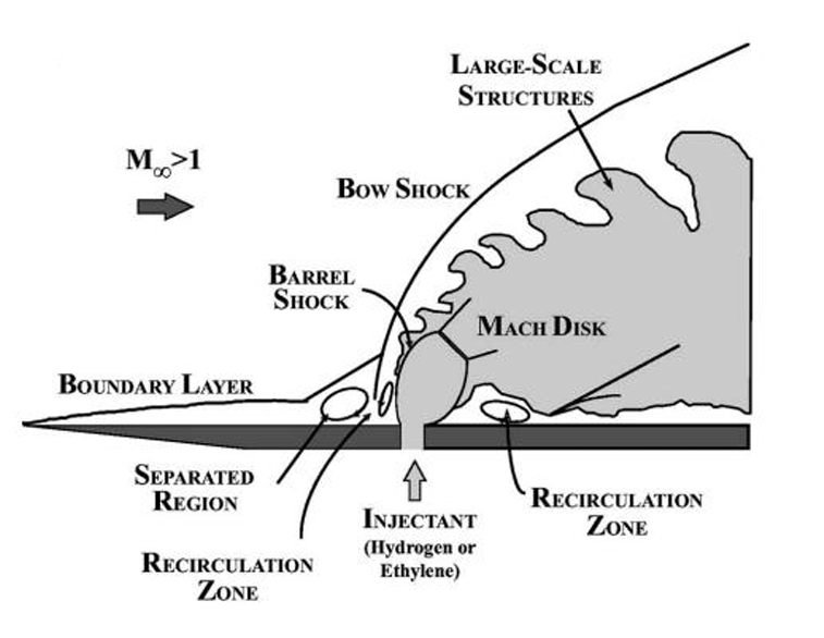
When a jet is injected into a supersonic crossflow, it creates an obstruction, leading to the formation of shock waves. The most prominent is the bow shock, which forms upstream due to the sudden deceleration of the supersonic freestream. This bow shock causes boundary layer separation, generating a recirculation region where jet and boundary layer fluids mix subsonically. Below this, the sonic line forms, marking the transition to subsonic speeds, which enhances fuel-air mixing and combustion stability.
The injected jet is typically under-expanded, meaning its exit pressure is higher than the surrounding crossflow. The jet Mach number is usually sonic, ensuring the mass flow rate remains independent of back pressure. Once injected, the jet forms a barrel shock, and at high pressure ratios, a Mach disk appears. Additionally, two upstream recirculation zones and two downstream recirculation zones develop due to flow separation and interaction with the freestream. These structures are key to efficient mixing and combustion.
The penetration height of the jet depends on the jet-to-freestream momentum flux ratio (J), which is directly proportional to the pressure ratio of the jet to the freestream. Increasing the jet pressure enhances penetration but also strengthens the bow shock, increasing stagnation pressure losses. High stagnation pressure losses reduce combustor efficiency, requiring an optimal pressure ratio that balances jet penetration and minimal losses.
Computational Setup: Geometry, Mesh, Boundary Conditions, and Solver Settings
The computational domain consists of a supersonic crossflow over a jet injector, as shown in the figure. The mesh is a nonuniform structured grid created using Pointwise, with finer resolution near the fuel inlet to accurately capture the interaction between the jet and the supersonic crossflow. This fine resolution is also maintained 70 mm upstream of the fuel inlet to correctly resolve boundary layer separation and ensure accurate shock capturing.
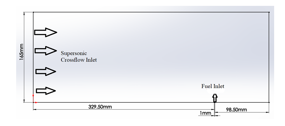
The incoming supersonic flow has a Mach number of \(3.75\), a static pressure of \(11090\) Pa, and consists of air (\(X_{O_2} = 0.209, X_{N_2} = 0.791\)). The fuel jet is injected perpendicularly into the crossflow at Mach \(1\), with a static pressure of \(196514.8\) Pa, and consists of pure nitrogen (\(X_{N_2} = 1.0\)). The pressure ratio of the jet to the freestream is \(17.72\), significantly influencing the jet penetration height and shock strength.
The boundary conditions applied to the computational domain are:
- Top boundary: Symmetry plane to simulate an infinitely wide flow
- Bottom boundary: No-slip wall to account for wall shear effects
- Inlet: Supersonic inflow with prescribed flow properties from freestream conditions
- Outlet: Supersonic pressure outlet allowing shock interactions to propagate without reflection
A steady-state simulation is performed using the k-omega SST turbulence model under non-reacting flow conditions. The key convergence criteria include:
- Residuals must drop below \(10^{-6}\)
- Mass flow rate imbalance must be less than \(0.05\%\) of the inlet mass flow rate
This setup ensures accurate resolution of shock interactions, boundary layer separation, and jet penetration dynamics. The jet penetration height is a crucial parameter in the analysis, as it influences fuel-air mixing efficiency in realistic scramjet applications. By analyzing the interaction between the jet and the supersonic crossflow at different pressure ratios, valuable insights can be gained into optimal injection strategies for efficient supersonic combustion.
Numerical Validation
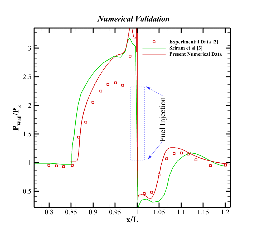
Wall pressure distributions are validated against experimental data (Link) and CFD results of Sriram et al. (Link). The wall pressure is non-dimensionalized using the freestream static pressure (\(11090\) Pa), and the x-coordinate is normalized by the distance from the supersonic inlet to the fuel injector centerline (\(330\) mm).
The separation point is where the pressure starts increasing due to boundary layer separation. Further downstream, pressure rises due to Primary Upstream Vortices (PUV) and spikes from Secondary Upstream Vortices (SUV). A sharp pressure drop occurs just after the jet, followed by fluctuations due to Primary and Secondary Downstream Vortices (PDV and SDV) and boundary layer reattachment.
The separation length is slightly under-predicted but remains close to experimental results. Upstream of the jet, wall pressure matches CFD results, while downstream, it closely follows experimental data. This confirms that the solver accurately captures boundary layer separation, jet penetration, and vortex structures.
Results and Discussion
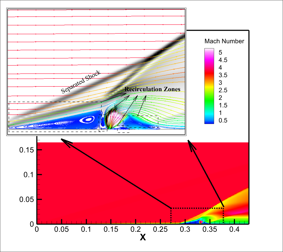
The figure below presents the Mach number contours and a zoomed-in view of streamlines near the fuel injection point. Four distinct recirculation zones are visible—two upstream and two downstream of the fuel injector. The upstream recirculation zones are critical as they provide a region where the fuel mixes with the incoming air subsonically, aiding flameholding in combustion applications.
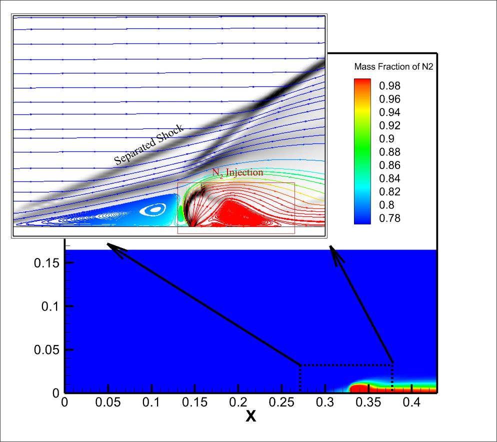
The following figure illustrates fuel penetration in the supersonic crossflow using mass fraction contours of nitrogen. The zoomed-in streamlines reveal the distribution of the injected fuel. At the freestream inlet, the nitrogen mass fraction is 0.78, consistent with the boundary conditions. The injected fuel remains concentrated near the wall, leading to poor mixing with the air.
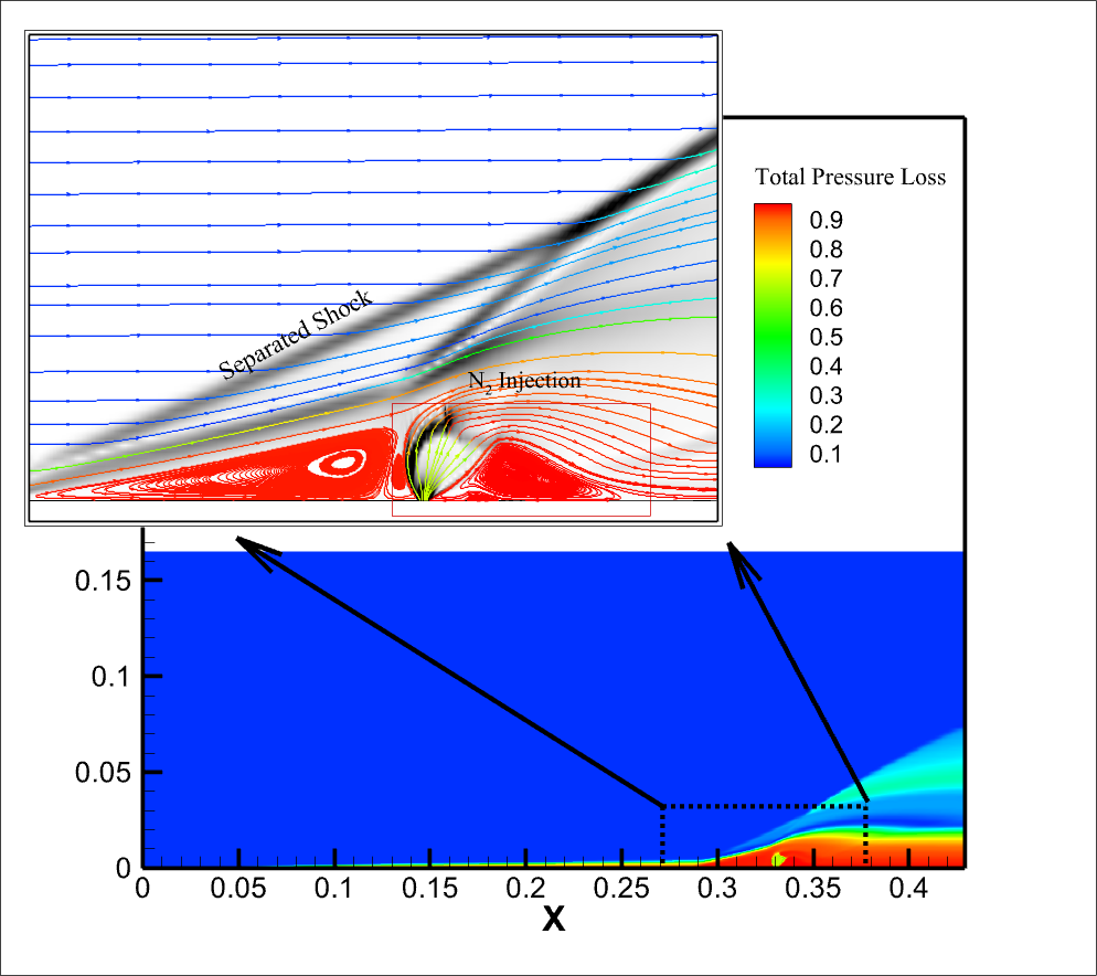
The final figure displays the stagnation pressure loss across the computational domain. The stagnation pressure is non-dimensionalized using the incoming air stagnation pressure (1199957.95 Pa) and subtracted from 1, so higher values indicate greater losses. As expected, maximum stagnation pressure losses occur near the fuel injection region, where the bow shock forms. The shock-induced irreversibilities contribute to pressure losses, impacting combustor efficiency.
Analysis of the Sonic Line and Separation Shock
The figure below shows the Mach number contours, highlighting the sonic line and separation shock. The sonic line marks the boundary between subsonic and supersonic regions, while the separation shock forms due to boundary layer detachment caused by jet obstruction.
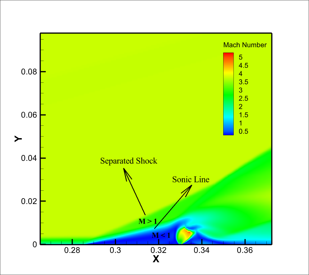
An interesting observation is that the sonic line and the region below resemble a wedge in supersonic flow, with the separation shock behaving like an oblique shock. The figure below visually compares this fluidic wedge to a geometric wedge-induced oblique shock. The θ-β-M relation is used to verify that the separation shock angle matches the oblique shock angle.
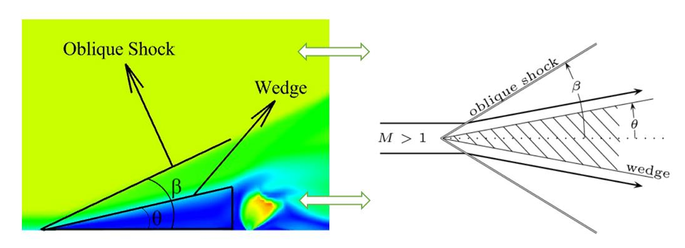
This discovery suggests that the fluidic pylon, formed naturally due to jet interaction, behaves similarly to geometric pylons used in combustors. Further investigations focus on how its properties can be controlled to enhance fuel-air mixing efficiency.
Effect of Pressure Ratio and Incoming Mach Number on the Fluidic Pylon
The properties of the fluidic pylon were analyzed by varying both the pressure ratio (jet-to-freestream) and the incoming Mach number while observing changes in the sonic line angle and separation shock behavior.
Increasing the pressure ratio leads to higher jet penetration and a longer separation length, effectively increasing the base and height of the fluidic pylon. However, the sonic line angle remains unchanged, meaning the fundamental flow structure remains stable despite increased jet obstruction.
Increasing the incoming Mach number at a constant pressure ratio causes a decrease in the sonic line angle, leading to a lower separation shock angle. This follows the expected trend from compressible flow shock relations, where a higher Mach number results in weaker shock angles.
These results confirm that while pressure ratio influences jet penetration and separation, the Mach number directly affects the shock system geometry.
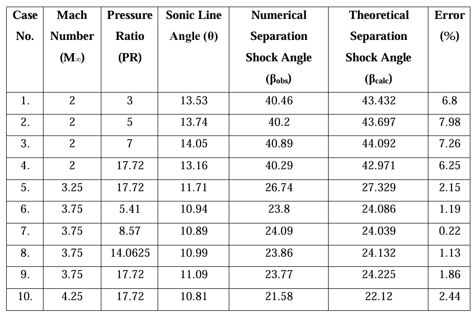
This analysis highlights how pressure ratio and Mach number collectively define the shape and strength of the fluidic pylon, with potential applications in optimizing fuel-air mixing in supersonic combustion systems.
Effect of Fuel Density and Velocity
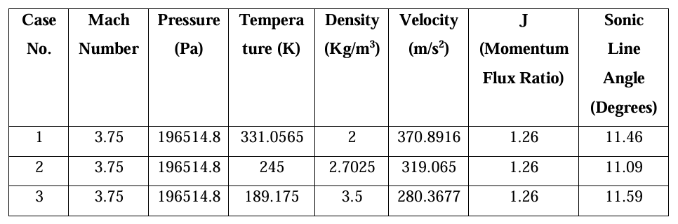
Additional simulations explored changes in fuel density and velocity, while keeping the momentum flux ratio constant. Findings confirm that sonic line angle remains unchanged, while the separation shock follows the θ-β-M relation.
Summary of Findings
- Sonic line angle remains constant with increasing pressure ratio, while penetration height and separation length increase.
- Sonic line angle decreases with increasing freestream Mach number, reducing the separation shock angle.
- Fuel density and velocity changes do not alter the sonic line angle, and the separation shock continues to follow compressible flow relations.
This analysis highlights the role of the fluidic pylon in influencing shock structures and fuel-air mixing efficiency, paving the way for further optimization in supersonic combustion applications.